Processing of Cage Pocket and Lock Claw of Cylindrical Roller Bearing crafts improvement
In order to prevent loose sleeves or rollers from falling off during the handling and installation of cylindrical roller bearings, locking points or locking claws [1], are often designed around the pockets of the cage to ensure that the cage, rollers, and rings are not locked after the bearing is assembled. External forces are inseparable [2]. There are many pockets in the cage, and there are locking claws on both sides of each pocket. The symmetry and locking amount of the locking claws directly affect the performance of the bearing. Due to the poor stability and consistency of the processing quality of the cage lock claws, it often occurs that the locking amount of the pocket hole is too small or the consistency of the locking amount is poor, causing the roller to fall off, and the bearing rotation is inflexible due to the excessive locking amount [3], and the bearing scrap rate High, batch repair ratio is high, so it is necessary to study the processing technology of cylindrical roller bearing cage pocket lock claw, and put forward corresponding improvement measures.
1 Analysis of the original process and existing problems
1.1 Original process
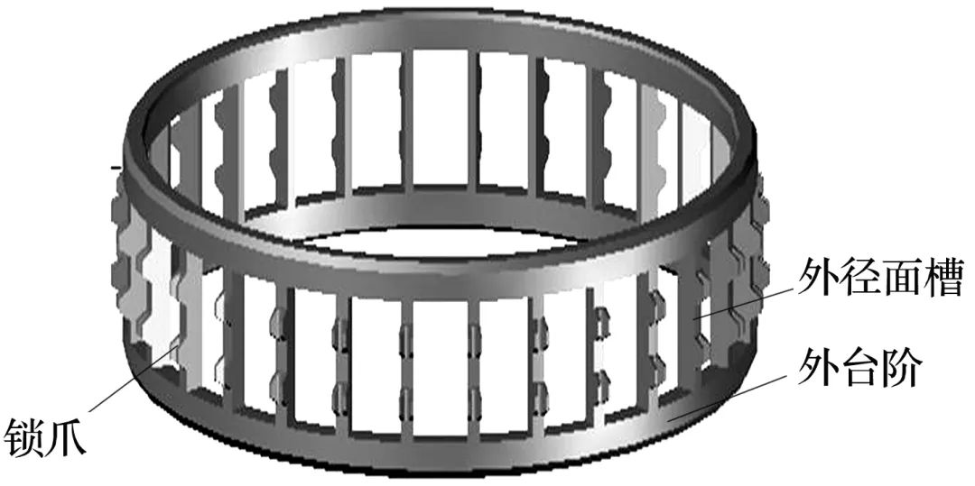
The locking claw structure of the cylindrical roller bearing cage [4] is shown in Figure 1, and its processing flow is as follows: rough turning → quenching and tempering → fine turning → marking → turning outer diameter surface groove → drilling and milling → drawing Square hole → final grinding inner diameter surface → outer steps and chamfering → deburring → milling step claws → deburring → finishing → splitting claws → cleaning → fluorescent magnetic particle inspection → cleaning → final inspection → silver plating → dynamic balancing → cleaning → Package.


Fig.1 Structural schematic diagram of locking claw of cylindrical roller bearing cage
1.2 Existing problems
1.2.1 Drilling, milling, and drawing pocket holes
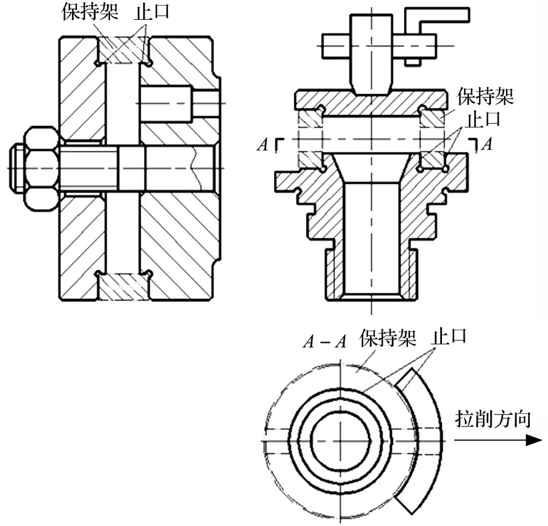
The pocket hole is first drilled and milled by a machining center, and then broached by a broaching machine. The drilling and milling process adopts the radial drilling die tooling, and the broaching process adopts the drawing square hole die tooling, as shown in Figure 2, both adopt the inner diameter surface and end face positioning of the cage. There is a clearance fit between the tooling and the cage, the basic size of the mating seam is the same, the tolerance of the inner diameter of the cage is 0-0.1 mm, the tolerance of the mating seam of the tooling is -0.04--0.02 mm and the fit clearance is 0.02- 0.14mm. The coaxial of the cage and the tooling is poor, and the circumferential position of the pocket hole cannot be guaranteed when the cage rotates with the tooling circumference in equal parts.

(a) Radial drilling template (b) Draw square hole template
Fig.2 Tooling for drilling, milling, and drawing of pocket
1.2.2 Milling jaws
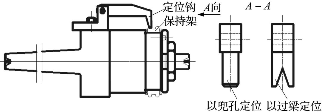
The schematic diagram of tooling for milling jaws is shown in Figure 3a. There is a positioning hook on the milling jaw mold, and a rectangular or circular positioning column (Figure 3b) is designed to match the size of the pocket hole. Insert it into the pocket hole to limit the circumferential movement of the cage. In order to make the lintel be processed directly above the cage, the positioning column and the machine table are in an inclined state during work, which is not easy to adjust. The symmetry of the locking claws after the milling claws is poor, and the thickness is uneven, which leads to the two locking claws facing each other when splitting the claws. The degree of curvature inside the pockets is inconsistent, and there is a problem that one of the adjacent pockets has too much lock and the other has too little lock.

(a) Milling jaw mold (b) Positioning column (c) V-shaped positioning groove
Fig.3 Tooling for milling of claw of pocket
1.2.3 Claw
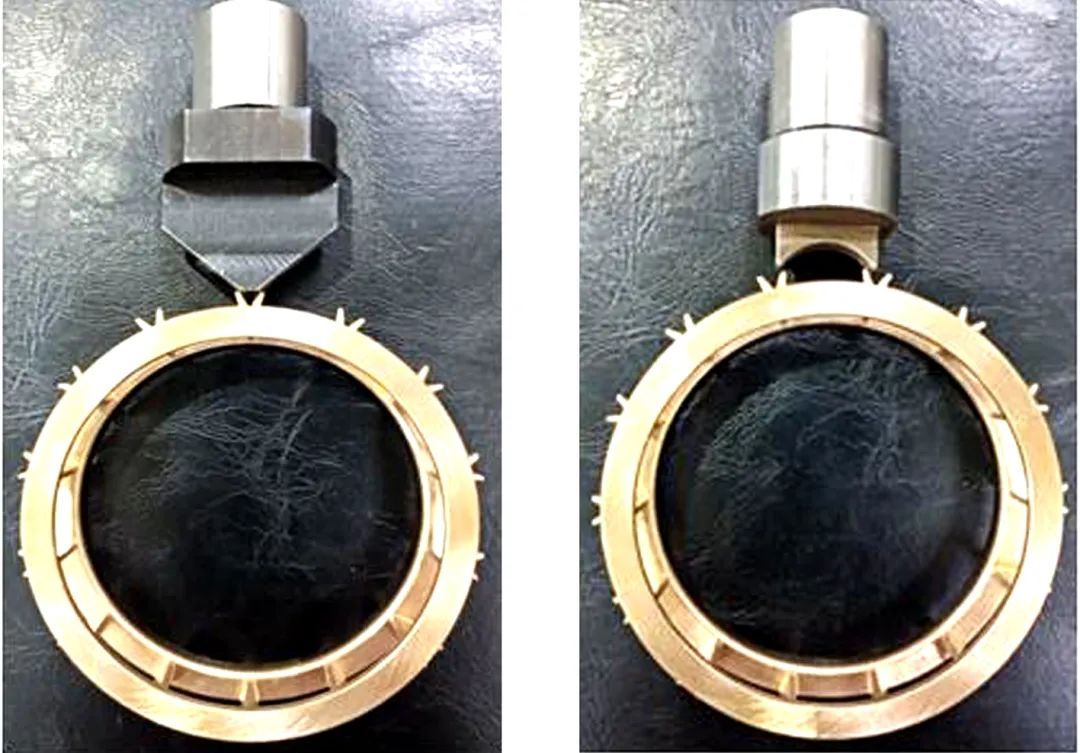
The single-tapered punch for splitting claws is shown in Figure 4a. The punch punches two locking claws on the same lintel at one time, and the locking claws on both sides of the same pocket hole need to be punched twice. The difference in the circumference of the pocket hole makes the width of the lintel uneven, and the thickness of the locking claw is different after the claw is split, resulting in inconsistent bending of the locking claw, and finally makes the rollers distributed unevenly along the circumference [5].

(a) before optimization (b) after optimization
Fig.4 Tooling for splitting of claw of pocket
2 Improvement measures
1) Before drilling and milling, increase the process of grinding two planes, finely grinding the outer diameter surface, finishing the inner diameter surface, or finely grinding the inner diameter surface to improve the accuracy of the positioning surface of the cage and improve the roundness and wall thickness difference of the rotary surface. Drilling and milling holes, drawing square holes, milling claws, splitting claws, etc. provide good positioning reference and precision reserves. The optimized process flow is: rough turning forming→quenching and tempering→fine turning forming→grinding two planes→fine grinding outer diameter surface→finish turning inner diameter surface or fine grinding inner diameter surface→marking→turning groove on outer diameter surface→drilling and milling Hole → square hole → final grinding inner diameter surface → outer step and chamfering → deburring → milling step claw → deburring → polishing → splitting claw → cleaning → fluorescent magnetic particle flaw detection → cleaning → final inspection → silver plating → dynamic balance → Cleaning → Packaging.
2) Change the gap fit between the radial drilling mold and the square hole mold and the cage to a transition fit, the fit gap is -0.01 ~ +0.04 mm, and at the same time reduce the shape and position accuracy of the mating lip surface relative to the tooling installation surface from 0.100 mm to 0.005 mm. In addition, in order to control the fit clearance, the positioning surface of the cage is matched with the tooling, that is, when the size of the positioning surface of the cage is processed, the tooling of the following process is adapted and processed, and the cage and the tooling are matched as far as possible within the scope of the process requirements. , to ensure the circumferential position of the pocket.
3) When milling claws, the pocket positioning is changed to the lintel positioning, and the positioning column is changed to a V-shaped positioning groove (Fig. 3c). The V-shaped positioning groove is stuck on the lintel between the two pocket holes to limit the cage The circumferential movement improves the positioning accuracy by improving the symmetry of the V-shaped groove, thereby improving the symmetry of the locking pawl.
4) Change the splitting claw from a single conical punch to a double punch structure (Figure 4b), and use the pre-processed pocket between the two locking claws to achieve circumferential positioning. The pocket is located above the cage and is easy to adjust, the locking claws on both sides of each pocket only need to be stamped once, which can ensure the symmetry of the locking claws and the relative position of the locking claws and the pocket holes, and avoid the problem of inconsistent bending degree of the locking claws caused by uneven width of the lintel [6]. In addition, the processing quality and symmetry of the punch surface are easier to guarantee, which further improves the processing quality of the cage-splitting claw.
3 Actual processing effect
The cylindrical roller-bearing cage pockets processed by the improved process have a high consistency of lock volume, stable processing quality, and a nearly 60% increase in processing efficiency, avoiding repairs caused by lock volume problems. This processing method can be extended to the processing of other cylindrical roller-bearing cage pocket lock claws.


